Desert Online General Trading LLC
Dubai, United Arab Emirates
Desert Online General Trading LLC
Dubai, United Arab Emirates


⚡ Elevate your Raspberry Pi Pico projects with instant GPIO clarity!
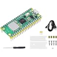
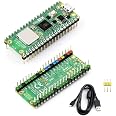
The Freenove Breakout Board is a precision-engineered terminal block shield compatible with all Raspberry Pi Pico models. Featuring independent GPIO status LEDs and clearly labeled pins, it streamlines prototyping by providing real-time feedback and secure connections. Ideal for professionals and makers seeking efficient, reliable hardware expansion.
| Processor | none |
| Brand | FREENOVE |
| Series | FNK0081 |
| Item model number | FNK0081 |
| Operating System | Debian |
| Item Weight | 2.11 ounces |
| Package Dimensions | 4.96 x 3.23 x 1.06 inches |
| Processor Brand | freenove |
| Number of Processors | 1 |
| Computer Memory Type | SRAM |
| Manufacturer | Freenove |
| ASIN | B0BFB53Y2N |
| Date First Available | September 14, 2022 |
Trustpilot
Hace 2 semanas
Hace 1 mes
Hace 2 semanas
Hace 1 mes