We remain fully operational. Our teams are working around the clock to ensure your deliveries continue safely.

Descargar la aplicación


Servicios al cliente
Sobre nosotros
Copyright © 2025 Desertcart Holdings Limited
Descargar la aplicación
Buy anything from 5,000+ international stores. One checkout price. No surprise fees. Join 2M+ shoppers on Desertcart.
Desertcart purchases this item on your behalf and handles shipping, customs, and support to Nicaragua.
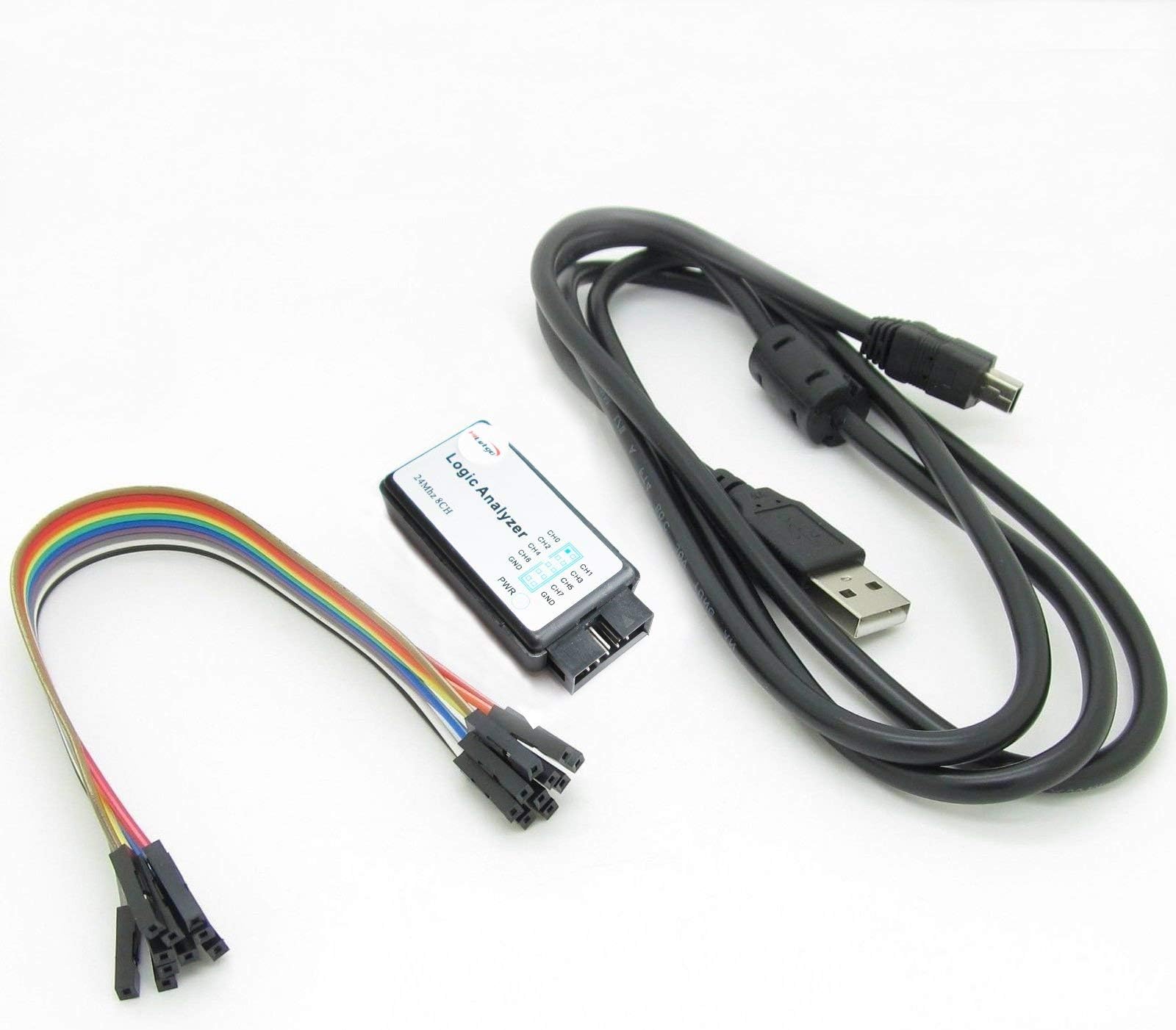
⚙️ Unlock the power of precision debugging with 24 MHz speed and 8-channel insight!
The HiLetgo USB Logic Analyzer is a professional-grade debugging tool featuring an 8-channel input and a maximum sampling rate of 24 MHz. It supports a wide input voltage range (-0.5V to 5.25V), making it compatible with various digital systems including 5V, 3.3V, and 2.5V logic levels. Equipped with USB Type-A connectivity and a compact design, it is ideal for embedded system developers and hardware engineers seeking reliable, high-speed signal analysis.
| ASIN | B077LSG5P2 |
| Best Sellers Rank | 134,033 in Business, Industry & Science ( See Top 100 in Business, Industry & Science ) 162 in Lab Oscilloscopes |
| Brand | HiLetgo |
| Cable Type | USB |
| Colour | Gray |
| Compatible Devices | Modem |
| Compatible Phone Models | No Compatible Phone Models |
| Connectivity Technology | USB |
| Connector Gender | Male |
| Connector Type | USB Type A |
| Customer Reviews | 4.5 4.5 out of 5 stars (537) |
| Data Transfer Rate | 24 Megabits Per Second |
| Frequency | 24 MHz |
| Item Shape | Round |
| Item Weight | 0.07 Kilograms |
| Manufacturer | HiLetgo |
| Model Name | LA-usb |
| Model Number | 3-01-0015 |
| Number of Items | 1 |
| Number of Pins | 4 |
| Other Special Features of the Product | Low Voltage |
| Recommended Uses For Product | digital signal analysis, embedded systems debugging, hardware development and testing |
| Unit Count | 1.0 count |
S**D
Functionally, this is a very good device for what it is intended, i.e., capturing signals at a low cost. As far as usability is concerened, you do need to get few things done in order to set it up, it would not be too difficult for anyone interested in this device. Thankfully, a lot of information is available on the NET. It is easy to use if you are already familiar with these type of devices, which I think 99% of users who have bought this device would be. If you watch the teardown of this device, it is built quite nicely.
F**B
I attached this logic analyzer to an old modem's UART and was able to capture the modem's boot process using PulseView. The device was recognized as 'Saleae'. This is a great device for hobbyists: basic, simple and very affordable. I am happy with this purachase
C**R
Summary Pros - inexpensive, works well with free open source software Cons - no on board capture buffer, no probes included This is a good little logic analyzer for the home hobbyist or even a small development team. The hardware uses a CY7C68013A microcontroller (an 8051 MCU core with an integrated USB 2.0 interface). It comes with a USB A to mini USB B cable and some short jumpers wires. It is powered by USB so there is no other power supply to deal with. There is no on board capture buffer so your computer needs to be fast enough to receive the data as it comes over USB. With most systems that shouldn’t be an issue providing you are not doing any other intensive tasks, particularly those that use USB, at the same time. Trying to run all 8 channels at 24Mhz though could be an issue on some systems. Looking at the board, there isn’t any input buffering other than series resistors. Care must be taken not to expose the channel inputs to voltages that could damage the on board microcontroller. There is no software included, but one can download the open source sigrok/PulseView which fully supports this device. I tested it with PulseView 0.4.1 on a Windows 10 system and it was recognized as “Saleae Logic” analyzer (an older name brand analyzer). The only part that could be slightly tricky to getting PulseView working is installing the WinUSB driver using Zadig. If you are unfamiliar with Zadig, you can read about it on the sigrok wiki area for windows. Since this board emulates a “Saleae Logic”, there are also commercial software offerings that should work with it. I did an initial test using two channels simultaneously reading a 115200 bps data stream (sample rate set to 500kHz) and it worked flawlessly. PulseView easily decoded the ASCII data once configured. I again captured the same stream setting at 24Mhz (which is way over sampled for the data stream) just to see what it would do, and it worked fine showing the much more frequent sample rate. I’m not aware of a way to setup anything but a simple trigger to start/stop capture using PulseView. That is a software limitation if you are trying to catch a more complex event that occurs infrequently. The jumper wires that came with it are of limited use unless you always have available header pins to connect to in your circuit (doubtful). I suggest ordering a set of “logic analyzer test clips” to complete your setup.
B**N
Good,It's working I doubted but no problem working fine.
N**K
This logic analyzer works perfectly - well worth the cost. It’s compatible with Logic software package and helped solve a rather complex bus protocol I needed to reverse engineer.
Trustpilot
Hace 3 semanas
Hace 3 semanas